Current Standards and Potential Future Advancements in the Spatial Resolution Development of Cardiac CT
Author'(s): Majed Dwaik and Sami Smerat*
1Istshari Arab Hospital, Radiologic Technologist, Ramallah.
2Dean Medical College and Health Science, Palestine Polytechnic University, Hebron, Palestine.
*Correspondence:
Sami Smerat, Istshari Arab Hospital, Radiologic technologist, Ramallah.
Received: 20 Jan 2023; Accepted: 26 Feb 2023; Published: 03 Mar 2023
Citation: Dwaik M, Smerat S. Current Standards and Potential Future Advancements in the Spatial Resolution Development of Cardiac CT. Cardiol Vasc Res. 2023; 7(1): 1-5.
Keywords
Introduction
Since the development of computed tomography (CT), Imaging specialists have faced substantial difficulties in presenting coronary arteries because the coronary arteries of the heart, which beat fast, have a small diameter. Since the debut of the first generation of CT in 1972, numerous technological advancements have taken place. One of the most important developments was the increase in rotation speed, which resulted in better temporal resolution and spatial resolution along the z axis thanks to the use of submillimeter collimations with extended volumetric acquisitions. The first hopeful findings in the field of cardiology were attained with the advent of 16-slice CT scanners, followed shortly by 64-slice CT scanners [1].
Despite the fact that the two methods have different goals, invasive coronary angiography (ICA) and cardiac computed tomography (CCT) were initially contrasted. Despite ICA's higher spatial (0.1- 0.2 mm, 50 lp/cm) and temporal (20 ms) resolution, it is important to underline the unmistakable benefits of the non-invasive CCT technique [2].
The picture quality and resilience of CCT have been gradually implemented by technological advancement along with advances in spatial, temporal, and contrast resolution (Table 1). (Figure 1). Plaque characterization, functional research, and dosage reduction are the current CCT problems.
Methods
The capacity to tell two nearby structures apart is referred to as spatial resolution. It is affected by a number of variables, including artifacts, filters, reconstruction parameters, detectors, thickness, and pitch. Inadequate spatial resolution may impair the ability to evaluate coronary arteries, particularly more distal (and hence smaller) branches, as well as to detect and quantify coronary stenosis. Inadequate spatial resolution can also lead to false positives and poor specificity can result from partial volume artifacts, which can also cause blooming aberrations and overestimation of coronary artery stenosis [3]. Spatial resolution was consequently the most important hardware problem to be solved in order to enable and then enhance the imaging of coronary arteries. One of the main elements that influence spatial resolution is detectors. Incoming photons that have already gone through the object being investigated are converted by the detector, an X-ray sensor, into an electrical signal that is picked up by a data-gathering device. An analog-to-digital converter then collects, amplifies, and converts this signal into digital data [4]. After a complex series of mathematical calculations, the raw data will then be linked to the pertinent spatial position given by an axis system (x, y, and z) [4]. Slice thickness reflects the z axis' relationship to the longitudinal axis, the x and y axes' relationship to the transverse plane (i.e., axial), which reflects the sides of the pixel that make up a matrix, and the three voxel measurements together produce a three- dimensional object. For measuring object dimensions, spatial frequency with the unit "line pairs per centimeter" is employed [5]. The global z-axis (or longitudinal) coverage increases with the number of detector rows, which relies on the detector's width and pitch. Fewer rotations are required to cover the heart volume as detector z-coverage increases [6].
The first significant advancement in CT cardiac imaging was the switch from 4- to 16-slice CT scanner detectors with improved collimation and z-axis coverage, as well as an increase in the minimum spatial resolution from 1 to 0.6 mm [7]. The detector rows grew in number during the ensuing years, a phenomenon known as "slice's war" [8]. Intended to increase the number of detector rows throughout the future years [8]. From 0.5 to 0.4 mm in a 64-slice CT to a 128-slice scanner to 0.35 mm in a 320-slice CT scanner to 0.17 mm in a 640-slice CT scanner, the spatial resolution increased [7,9]. The use of a z-flying focus point technology is another benefit [8], Some manufacturers have developed a CT with 128 detector slices that produces a picture that is comparable to one with 256 slices (160 mm). For each projection, this approach permits the focal spot to change along the z-axis in order to produce two overlapping slices [10]. However, when the detector is very wide, the reconstructed object gradually deforms, starting out very mildly near the scanner's isocenter and increasing in severity as it approaches the edges of the field of view. It may seem straightforward to think that by simply raising the detector row count, the CT table might be moved without having to move the heart, but this is not the case (FOV). Despite the fact that correcting techniques have been developed over time, the majority of very wide detector scanners cannot employ the entire detector when utilized for conventional body CT applications, and this issue has not yet been entirely overcome. X-ray scatter is a challenge of increased detector z-coverage [6]. The similar problem exists with flat panel CTs (FPCT). The FPCT is characterised by a single big detector (composed of cesium iodide-based scintillation crystals and an amorphous selenium matrix), which allows for extensive z-axis coverage and has a matrix divided into 2048 × 1536 voxels, but has a low contrast resolution due to X-ray scatter [8]. Shorter breath-holding times are needed for cardiac scanning because to a significant increase in z-coverage since the introduction of the first 4-slice CT scanner. As a result, The CCT was no longer significantly constrained by the detector coverage. However, it should be noted that the number of heartbeats that contribute to the creation of the image declines as detector z-coverage increases. Additionally, the investigation of dynamic myocardial perfusion greatly benefits from a detector with a broad z-coverage [11]. The development of detectors has kept pace with CT technology to accommodate the rise in acquisition speed and tube peak power.
Accuracy, dynamic range, stability, uniformity, speed of response, quick afterglow, resolution, geometric efficiency, detector quantum efficiency, and cross talk are some of the properties detectors need to have in order to produce acceptable diagnostic image quality [12]. The higher speed, performance, and power of the detector were necessary due to the increased gantry speed. The anode angle was increased, the focal spot's physical power density was increased, and the detector cells and focal spots were reduced to improve spatial resolution [13]. The in-plane spatial resolution of a CT system is dependent on both the overall number of active detector channels in a detector row and their participation [6]. The effects of detector size, which have been increasingly significant in spatial resolution, have been one of the main pillars for the technological development of CT in recent decades. More detectors are needed in the z-axis due to the larger area to cover and the requirement for sub-millimetric acquisitions [14]. Clinical detectors have had the same size for a very long time, measuring 0.5–0.625 mm at the isocenter. Onishi et al. [15] assessed in-stent restenosis using a clinical CT scanner with energy integrating detectors of 0.25 mm diameter at the isocenter. To get a greater spatial resolution with a smaller detector, the focal spot size should be decreased [15]. Expanding the detector sampling is an additional method for enhancing spatial resolution [16-18]. Another need for the visualization of the coronary arteries is the isotropic sub- millimetric spatial resolution [19]. The quantity of active detector channels and their participation determine the in-plane spatial resolution of a CT scanner. In order to quadruple the number of samples captured in the scan FOV and increase spatial resolution, modern CT scanners employ techniques like quarter detector offset or in-plane flying focus point. Reduced aliasing artifacts are achieved by using the quarter detector offset [19]. By adjusting the location of the focused spot in the anode plate, the in-plane flying focal spot may do twice as many samples [6]. An improvement in resolution along the z-axis was one benefit of 64-slice CT scanners over earlier models; in fact, even thinner collimated slices are now possible. For the examination of coronary arteries, this evolution was essential. Although coronary stenosis, by-passes, and cardiac anatomy can be reliably assessed, 64-slice scanners' spatial resolution was not optimal for a clinical examination of intra-stent lumen. McCollough and further [20] demonstrated with the aid of a phantom model that the use of blocking detectors in the direction of the fan angle, in combination with a longitudinal deconvolution method and iterative reconstruction, allowed for good longitudinal resolution and increased dose efficiency.
In-stent evaluation in CCT is still difficult, especially with tiny and hyper dense (i.e., stents (not fully expanded) (Figure 2).Additionally, the detectors' makeup has evolved over time, and it has improved CT performance in recent years. At first, the detectors were mostly xenon gaseous detectors [21]. However, gaseous detectors have poor performance, therefore solid-state CT detectors are now the only ones in use. Ceramics constructed of CdWO4, yttrium, and gadolinium (Gd2O2S) can be used to create a solid-state CT detector [21], additionally, due to its conformation; it can be utilized in fourth-generation CT. A garnet- based substance detector was one of many novel materials tested to improve the effectiveness of the detectors. In comparison to a gadolinium ceramic detector, this one exhibits a reduction in noise and an improvement in spatial and temporal resolution along with a An afterglow that lasts 75% less time and has a 100-fold faster decay time (which is the rate of light emission after the stimulation) (defined as the amount of time required to reset the detector for a new excitation) [22]. Dual-energy computed tomography (DECT), which enables the simultaneous acquisition of different energy levels from an X-ray tube, can be performed using the garnet- based detector [22]. In cardiac imaging, where accuracy and speed are crucial, these novel qualities can be employed. Furthermore, it has been shown that garnet-based detectors enhance the evaluation of coronary stents by minimizing artifacts [22].
The Photon-Counting Detector CT must be listed among the recent research topics (PCD). With its extremely high spatial resolution (33 line pairs per centimeter), PCD is a new technology that has potential uses in the cardiovascular area, particularly for stent imaging. It has an improved contrast-to-noise ratio and the capacity to eliminate electronic noise, beam-hardening, and metal artifacts [23]. Although larger matrix (1,0241,024, 2,0482,048) are now accessible, larger matrix (1,0241,024) have long maintained the normal 512512 size in the majority of clinical applications. However, larger matrix requires more time to reconstruct, transfer, analyze, display, and store data [15]. Additionally, iterative reconstructions and filtering kernels can both impact spatial resolution. In order to lessen the blurring that results from rear projection alone, convolution filters are used. Each convolution kernel builds a filtered profile by using the values of surrounding pixels. Generally speaking, there are three basic kinds of kernel filters: regular, smooth, and sharp. Spatial resolution and noise are influenced by the type of filter used; Spatial resolution improves with sharper kernels and worsens with smoother ones, despite the fact that noise increases with sharp kernels (Figure 1).

Figure 1: Right coronary artery multiplanar reconstructions with smooth(A) and sharp (B) filtering showing calcified plaques (B).
For coronary calcifications and in-stent assessment, a higher spatial resolution is necessary. Kernels are used in filtered bac
projection (FBP), although low dose operations, especially in obese patients, cause an increase in visual noise [24]. Additionally, assuming the other parameters remain constant, employing smaller slice reconstructions may improve spatial resolution but at the cost of increased noise [25,26]. Progressively reconstructive (IR) were created to lessen noise and enhance image quality [27,28]. After generating fresh projection data from the images obtained from the FBP, IR compares it to the original data and applies noise adjustments. Iterations of this method are repeated multiple times [24]. As shown in the Compared to IR, which maintains adequate image quality while reducing dose [29]. Yang et al. [30] shown that IR improved in-stent restenosis evaluation in high pitch dual source CT (DSCT), with greater specificity (82% vs. 62%) and positive predictive value (66% vs. 50%) compared to FBP.
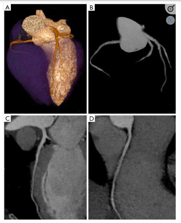
Figure 2: Coronary artery tree map and iterative reconstructions on a cardiac CT scan are shown in (A), (B), and (C, D), respectively.
Schindler et al. [31] shown that, despite the possibility of risk reclassification in a small sample of people, Agatston score quantification is not different between FBP and IR with relation to the use of IR for coronary artery calcium measurement. As measured by the IR versus FBP algorithm, the Agatston, volume, and, to a lesser extent, mass scores were all decreased., however, according to other investigations [31,32]. Obtaining a high-quality CCT image in this population of obese patients can be difficult, and in general, more radiation is needed to make up for the increased noise. In a regular protocol at 120 kV, Wang et al. [33] showed that IR provides for a maintained image quality with a noticeably lower radiation dosage (4.410.83 vs. 8.831.74 mSv) in obese patients.
As previously mentioned, IR has a number of benefits, such as reduced noise and radiation dose (Figure 2), but it also has certain drawbacks. Although they have gotten faster recently, the reconstruction processes take longer. Additionally, because IR images have a different aspect, they could lead to certain diagnostic errors in operators without enough training [28].
Another factor in spatial resolution is the pitch, which is calculated by dividing the amplitude of the detectors by the rate of the CT table's movement per gantry revolution [34]. Cardiovascular imaging in spiral mode requires low pitch since higher pitch causes gaps and high-quality 3D images with few artifacts require data overlap; a typical CCT pitch is between 0.2 and 0.4 depending on the patient's heart rate throughout the scan [14]. The possibility that the optimal phase—i.e., the phase of the cardiac cycle with the least amount of residual motion—will be identified and used for coronary artery assessment increases as well with a low pitch since it increases CT data redundancy along the cardiac cycle. However, one must always keep in mind that for pitch, a low an average larger radiation dose is required. In conclusion, coronary stent evaluation has issues because of their tiny size and the hyperdense. Substance they are made of; blooming artifacts result in false positives and have a reduced specificity. The hardening of the beam on the detector is caused by the presence of high-density structures. The best method for eliminating stent evaluation artifacts is still increasing spatial resolution; thin acquisition layers and a limited field of view are essential. Sharp kernels, IR, and DECT can all enhance in-stent examination [35].
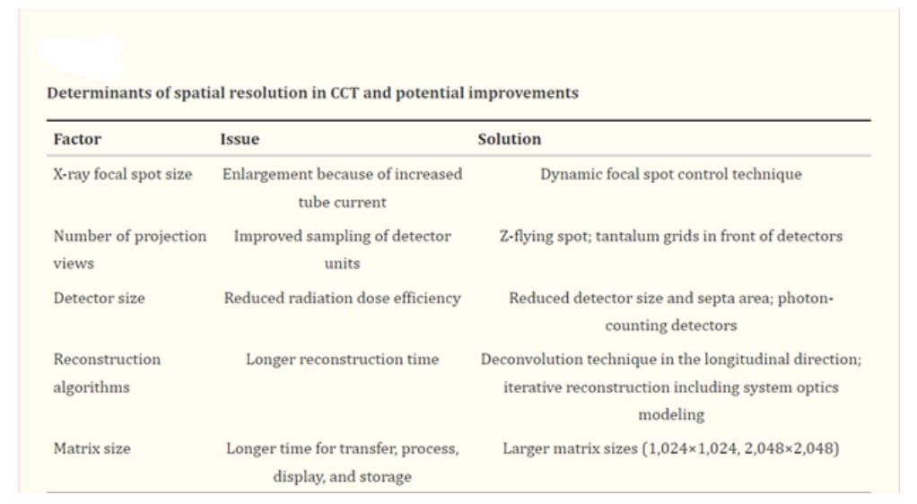
Main the factors that affect CCT's spatial resolution and prospective advancements are listed in Table 1.
Conclusion
We concentrated on the most recent methods for spatial improvement in this review. Although CCT produced excellent anatomic imaging results, revascularization of coronary artery stenosis and its functional significance should be addressed with hardware and software solutions.
References
- Cademartiri F, Runza G, Belgrano M, et al. Introduction to coronary imaging with 64-slice computed tomography. Radiol Med. 2005; 110: 16-41.
- Fattori R. La TC multidetettore nella diagnostica cardiovascolare. Milano, Italia: Springer. 2006.
- Machida H, Tanaka I, Fukui R, et al. Current and Novel Imaging Techniques in Coronary CT. RadioGraphics. 2015; 35: 991-1010.
- Goldman LW. Principles of CT: Multislice CT. J Nucl Med Technol. 2008; 36: 57-68.
- Wang J, Fleischmann D. Improving Spatial Resolution at CT: Development, Benefits, and Pitfalls. Radiology. 2018; 289: 261-262.
- Flohr TG, Raupach R, Bruder H, et al. Cardiac CT: How much can temporal resolution, spatial resolution, and volume coverage be improved?. J Cardiovasc Comput Tomogr. 2009; 3: 143-152.
- Schuleri KH, George RT, Lardo AC. Applications of cardiac multidetector CT beyond coronary angiography. Nat Rev Cardiol. 2009; 6: 699-710.
- Faggioni L, Paolicchi F, Neri E. Elementi di tomografia computerizzata. Milan, Italia: Springer. 2011.
- Available online: Healthcare-in-europe.com
- Halliburton S, Arbab-Zadeh A, Dey D, et al. State-of-the- art in CT hardware and scan modes for cardiovascular CT. J Cardiovasc Comput Tomogr. 2012; 6: 154-163.
- Ohnesorge BM, Flohr TG, Becker CR, et al. Multi-slice and Dual-source CT in Cardiac Imaging Principles-Protocols- Indications-Outlook. Berlino: Springer. 2006.
- Goldman LW. Principles of CT and the evolution of CT technology. In: Goldman LW, Fowlkes JB, editors. Categorical course in diagnostic radiology physics: CT and US cross sectional imaging. RSNA, Oak Brook, 2000. 124.
- Shefer E, Altman A, Behling R, et al. State of the Art of CT Detectors and Sources: A Literature Review. Curr Radiol Rep. 2013; 1: 76-91.
- Mahesh M, Cody DD. Physics of Cardiac Imaging with Multiple- Row Detector CT. RadioGraphics. 2007; 27: 1495-1509.
- Onishi H, Hori M, Ota T, et al. Phantom study of in-stent restenosis at high-spatial- resolution CT. Radiology. 2018; 289: 255-260.
- Flohr TG, Stierstorfer K, Ulzheimer S, et al. Image reconstruction and image quality evaluation for a 64-slice CT scanner with z-flying focal spot. Med Phys. 2005; 32: 2536- 2547.
- Flohr TG, Stierstorfer K, Süss C, et al. Novel ultrahigh resolution data acquisition and image reconstruction for multi- detector row CT. Med Phys. 2007; 34: 1712-1723.
- Tang X, Narayanan S, Hsieh J, et al. Enhancement of in-plane spatial resolution in volumetric Computed Tomography with focal spot wobbling - overcoming the constraint on number of projection views per gantry rotation. J Xray Sci Technol. 2010; 18: 251-265.
- Lin E, Alessio A. What are the basic concepts of temporal, contrast, and spatial resolution in cardiac CT?. J Cardiovasc Comput Tomogr. 2009; 3: 403-408.
- McCollough CH, Leng S, Sunnegardh J, et al. Spatial resolution improvement and dose reduction potential for inner ear CT imaging using a z-axis deconvolution technique. Med Phys. 2013; 40: 061904.
- Bushberg JT, Boone JM, Leidholdt EM, et al. The Essential Physics of Medical Imaging. Philadelphia: Lippincott Williams and Wilkins. 2011.
- Chaikriangkrai K, Choi SY, Nabi F, et al. Important advances in technology and unique applications to cardiovascular computed tomography. Methodist Debakey Cardiovasc J. 2014; 10: 152-158.
- Leng S, Bruesewitz M, Tao S, et al. Photon-counting Detector CT: System Design and Clinical Applications of an Emerging Technology. Radiographics. 2019; 39: 729-743.
- Schoepf UJ. CT of the Heart. Human Press. 2019.
- Kalisz K, Buethe J, Saboo SS, et al. Artifacts at Cardiac CT: Physics and Solutions. Radiographics. 2016; 36: 2064-2083.
- Kumamaru KK, Hoppel BE, Mather RT, et al. CT angiography: current technology and clinical use. Radiol Clin North Am. 2010; 48: 213-235.
- Willemink MJ, De Jong PA, Leiner T, et al. Iterative reconstruction techniques for computed tomography part 1: technical principles. Eur Radiol. 2013; 23: 1623-1631.
- Halliburton SS, Tanabe Y, Partovi S, et al. The role of advanced reconstruction algorithms in cardiac CT. Cardiovasc Diagn Ther. 2017; 7: 527-538.
- Jiang H. Computed Tomography: Principles, Design, Artifacts, and Recent Advances. Bellingham: Society of Photo Optical. 2015.
- Yang J, Yang X, De Cecco CN, et al. Iterative reconstruction improves detection of in-stent restenosis by high-pitch dual- source coronary CT angiography. Sci Rep. 2017; 7: 6956.
- Schindler A, Vliegenthart R, Schoepf UJ, et al. Iterative image reconstruction techniques for CT coronary artery calcium quantification: comparison with traditional filtered back projection in vitro and in vivo. Radiology. 2014; 270: 387- 393.
- Willemink MJ, Takx RA, De Jong PA, et al. The impact of CT radiation dose reduction and iterative reconstruction algorithms from four different vendors on coronary calcium scoring. Eur Radiol. 2014; 24: 2201-2212.
- Wang R, Schoepf UJ, Wu R, et al. Image quality and radiation dose of low dose coronary CT angiography in obese patients: sinogram affirmed iterative reconstruction versus filtered back projection. Eur J Radiol. 2012; 81: 3141-3145.
- Cademartiri F, Casolo G, Midiri M. La TC del cuore nella pratica clinica. Italia: Springer-Verlag. 2007.
- Mahnken AH. CT Imaging of Coronary Stents: Past, Present, and Future. ISRN Cardiol. 2012; 2012: 139823.